ORANGE CRATE DERBY CAR ASSEMBLY
Important! – Contact Bob Lechner before you begin working on a car 619 754-5089! We can loan you a car to copy while you build yours. (It makes it so much easier!) Plan to attend all 3 build a car clinics to get approval on brakes, steering and design elements before practice day!
The basic Orange Crate Derby car consists of 6 components
- Chassis or floorboard
- Front end “orange crate”
- Steering
- Brakes
- Seat and safety side panels
- Wheels
Download the Car Specifications
CHASSIS
The chassis or floorboard is made of wood 1 ½ inches thick, 6 feet long, and 19 inches wide, at least as far back as the front of the brake housing. It may be constructed of various widths of 2X wood such as 2X4, 2X6, etc. fastened together. 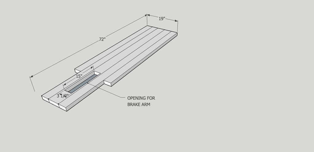 Chassis (click for larger view)
ORANGE CRATE
The front end “orange crate” is built from 2X2s and thin slats about 3 inches wide and about 3/8 inch thick. The supporting 2X2 frame is four sided at the front, and three sided at the back. The orange crate is attached to the front of the chassis and sits over the steering assembly. 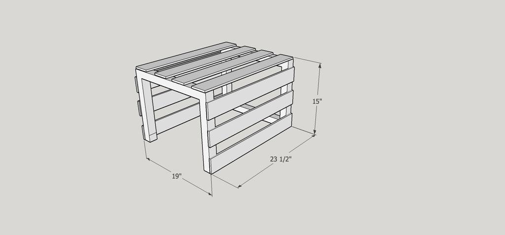 Crate (click for larger view)
STEERING
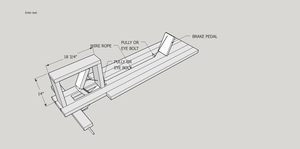
Steering is accomplished by a wheel and 1 inch wood dowel attached to the chassis and orange crate. A 1/16 to 1/8 inch wire rope is wound around the wood dowel and is led through pulleys to the ends of the front axle, which in turn is fastened to the chassis with a bolt so that it can pivot. 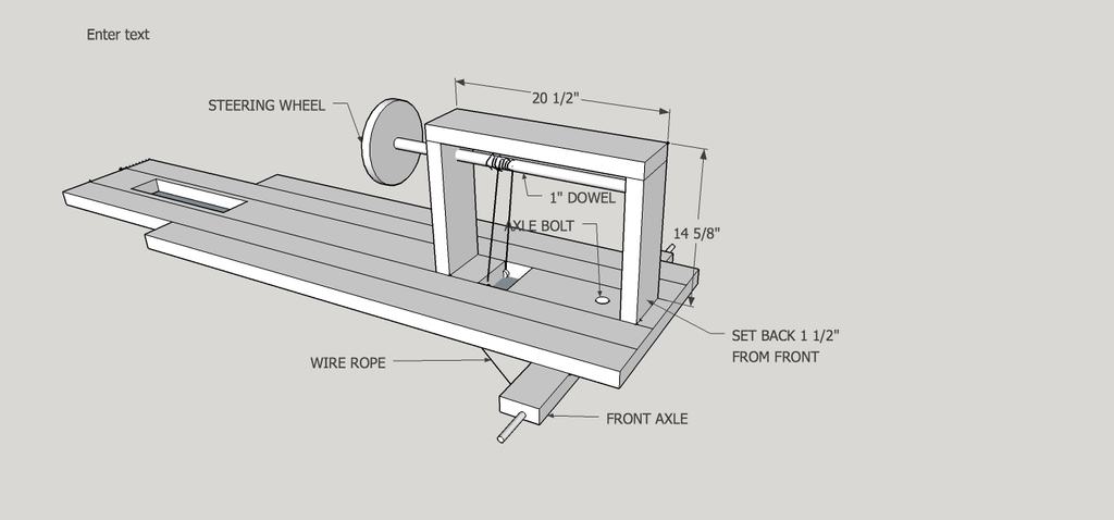 Steering (click for larger view)
Steering 3D view
The wire rope is attached to the wood dowel by first passing it through a hole drilled in the dowel, and then winding it around the dowel at least three times in each direction. Note that the wire rope must cross under the wood dowel and go to the opposite side of the car in order for the car to steer in the direction the wheel is turned.
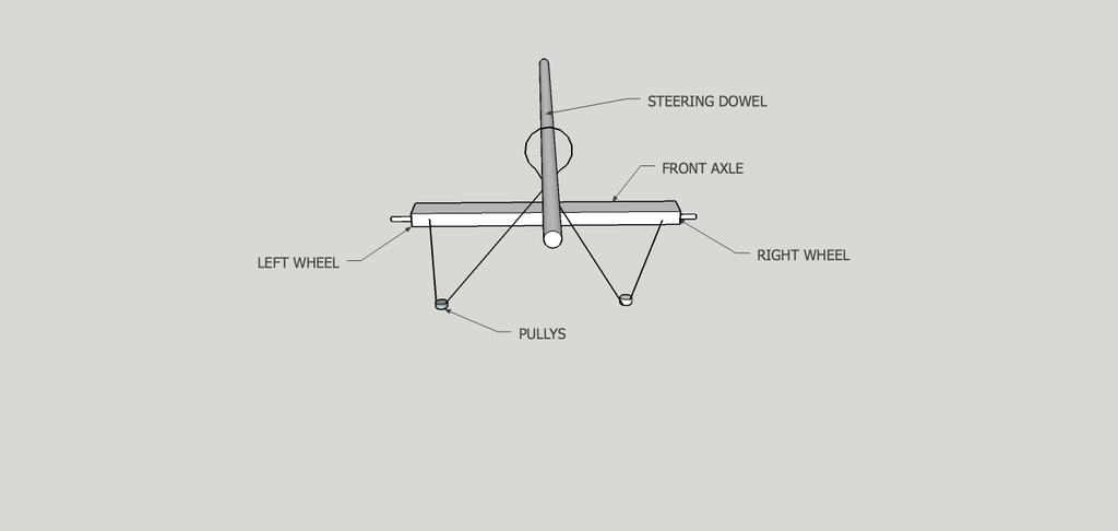 Steering wire rope (click for larger view)
The front axle must be constrained by a block of wood under the chassis so that the ends of the axle can only move a total of 3 inches. (1 ½ inches in each direction from straight ahead).
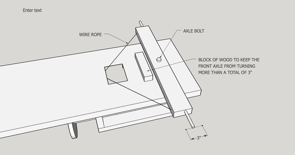 Front axle constraint (click for larger view)
BRAKES
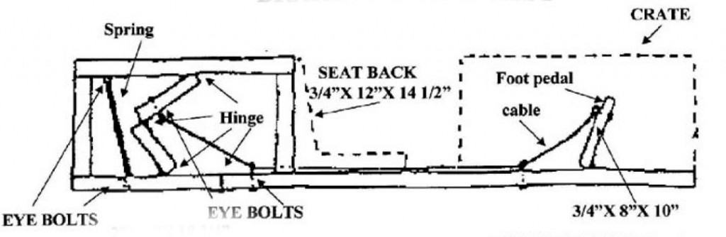
The brake system consists of three levers operated by a foot pedal. The levers are moved by the foot pedal by means of a wire rope run through pulleys or eye bolts. One of the levers, known as the brake arm, is attached to the chassis with a hinge, and had has a rubber pad attached to the other end. The other two levers are attached to each other, the brake arm, and the brake housing by hinges. The brake arm is attached to the brake housing with a spring.
 Brake A (click for larger view)
Brake and Seat Assembly, foot pedal up (click for larger view)
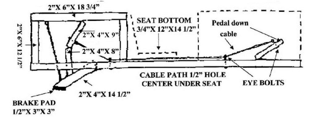
Brake and Seat Assembly, foot pedal down (click for larger view)
SEAT AND SAFETY SIDE PANELS
The seat is placed just in front of the brake housing, and consists of a back and bottom. It must be securely fastened to the chassis, but can be made adjustable so the car can be used by more than one driver. 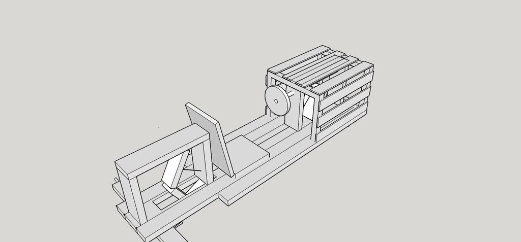 Seat (click for larger view)
Safety side panels are required for all new cars built, and it is recommended that older cars be retrofitted. This is a safety issue, and is why the chassis needs to be 19 inches wide to the front of the brake housing. The sides panels must be at least 10 inches high by the driver, and at least 6 inches high where it meets the orange crate.
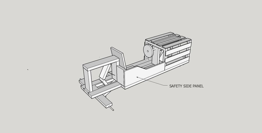 Side panel (click for larger view)
WHEELS
Wheels are 10 inch diameter ball bearing, rubber rimmed disks, mounted at the ends of 36 inch threaded rods, which in turn are fastened in a groove cut in the 2X4X29 ¾ inch wood axle. Care should be taken not to over-tighten the wheel retaining nuts. A good procedure is to finger tighten the first nut, then back it off about ½ turn before locking it place with the second nut. 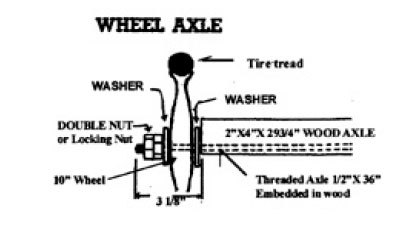 Wheel Axle Assembly (click for larger view)