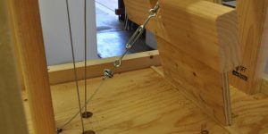
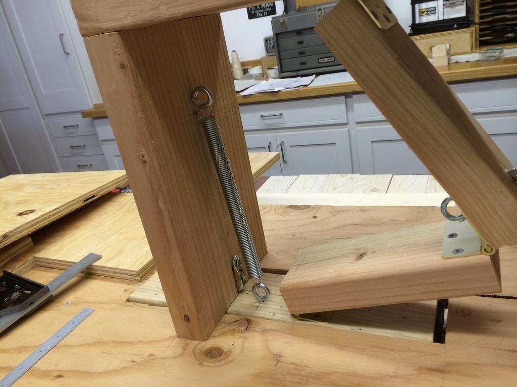
Once all the brake parts are assembled the brake cable and spring may be attached as shown in figure sk-26.
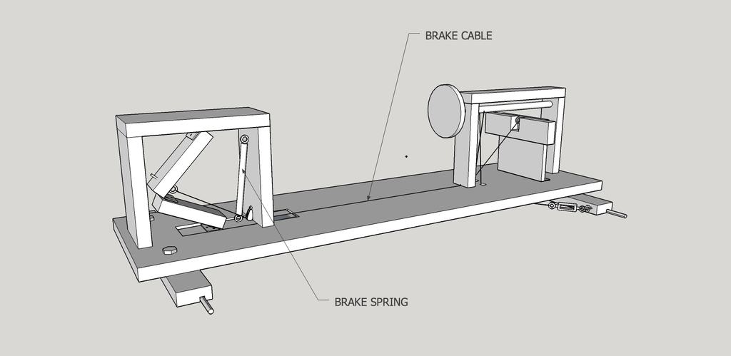
figure sk-26
Once all the brake parts are assembled the brake cable and spring may be attached as shown in figure sk-26.
figure sk-26
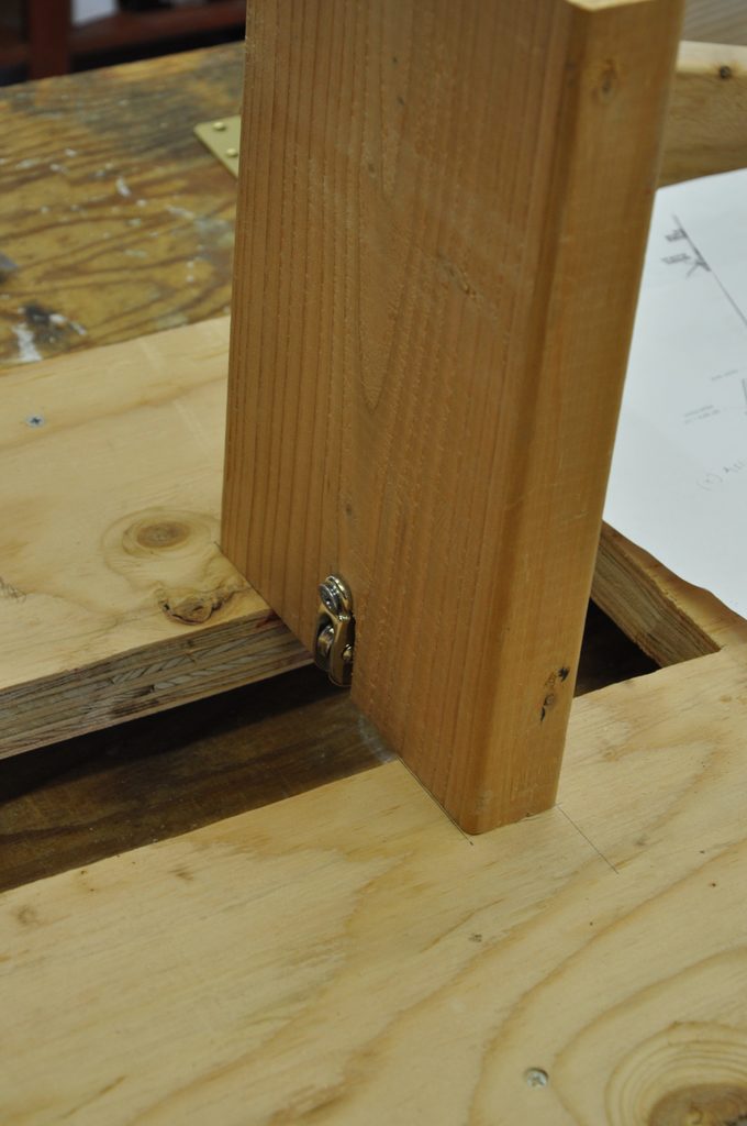
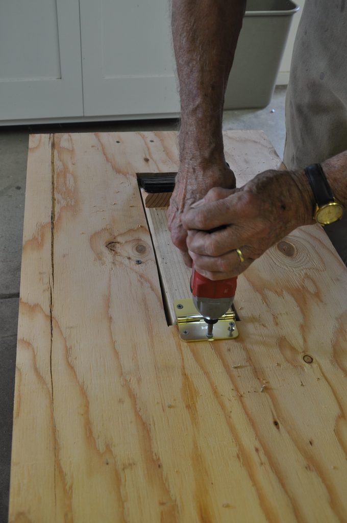
The brake pedal is made from a 8″ x 10″ piece of plywood with a piece of 2″ x 4″ fastened across its top. This pedal is fastened to the frame with two hinges. It has an eyebolt through its top part, to which the brake cable is fastened. The brake cable will go from the top of the brake pedal, through the eyebolt at the base of the rear steering frame support, under the seat, through the pulley at the base of the front brake housing support, and then is fastened to the eyebolt in the upper brake linkage arm in a later step.
Attach a spring to the back brake housing support eyebolt and the brake arm eyebolt. This is to retract the brake arm.
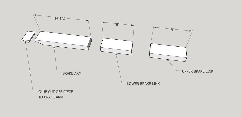
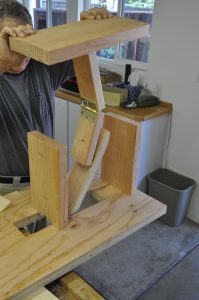
Cut three pieces of 2″ x 4″ 8′, 9″ and 14 1/2″ long. The 8″ and 9″ pieces will form the brake linkage and the 14 1/2″ piece is the brake arm. The arm and linkage assembly goes together as shown in figure sk-13 and is then fastened to the housing top as shown in figure 14.
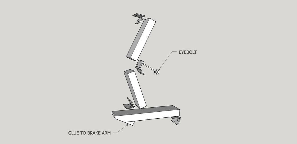
figure sk-13
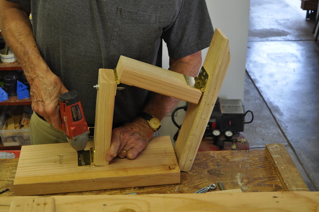
figure 14
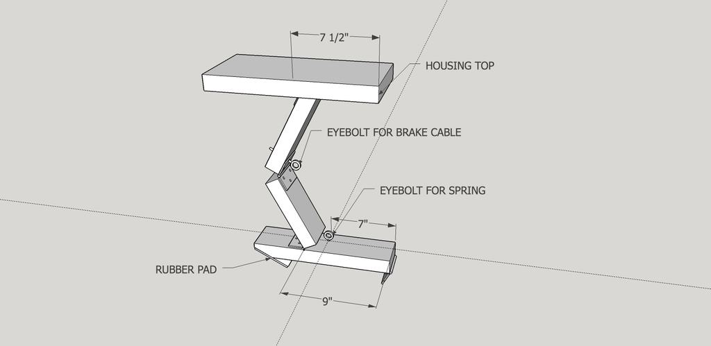
figure sk-15
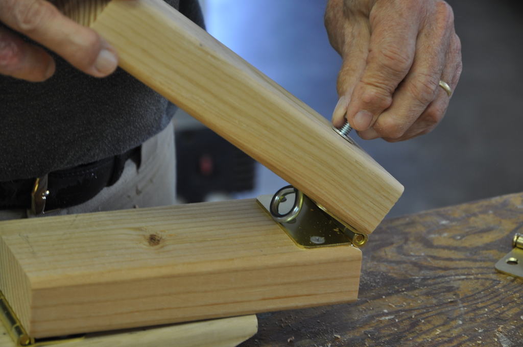
The brake arm, the upper and lower linkages and the brake housing top are joined together with hinges. The center hinge screw to the upper linkage is replaced with an eye bolt for the brake cable.
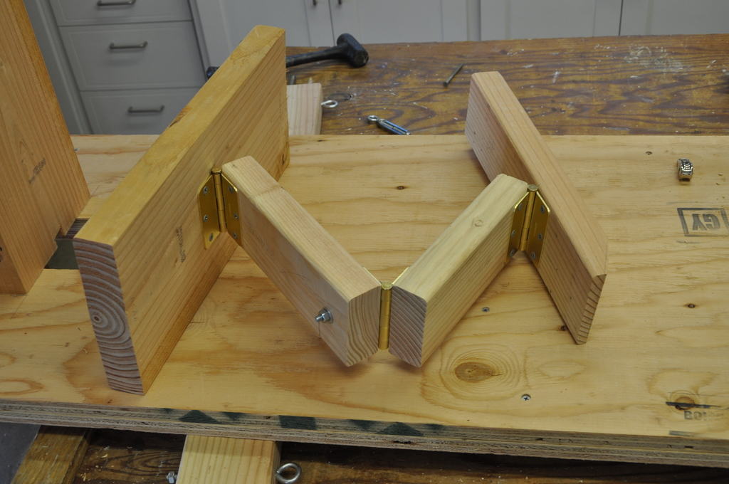
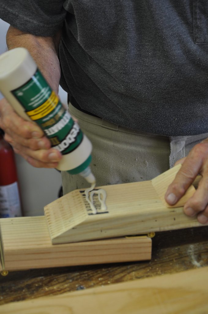
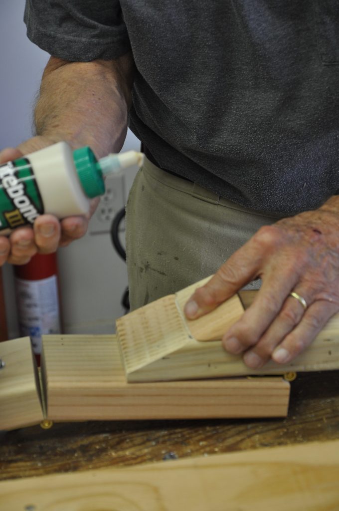
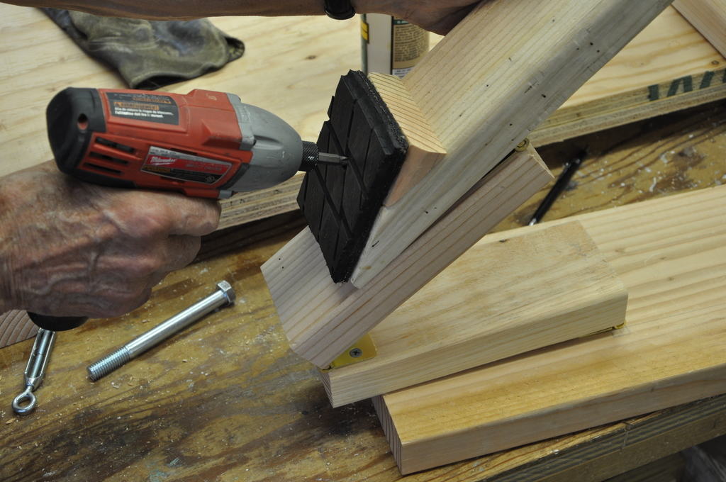
One end of the brake arm is cut at an angle, and the part that is cut off is glued back on the brake arm just behind the cut area. This forms the surface where the rubber brake pad is fastened.
 ,
,
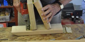
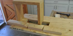
The brake arm linkage top assembly is lowered through the brake arm opening in the frame. The brake housing top is fastened to the two supports with lag bolts.
With the frame turned over, the brake arm is fastened to the frame with a hinge.
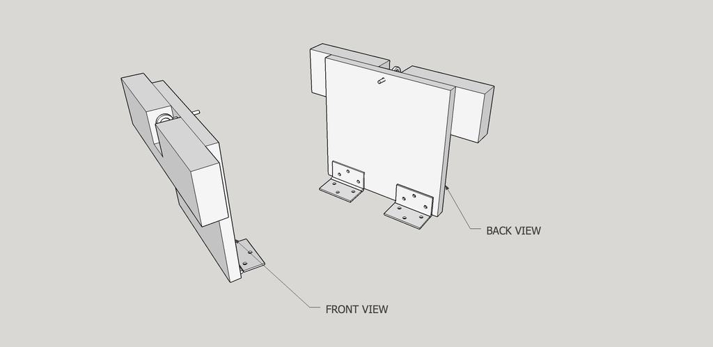
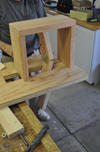
Cut two brake housing supports and one top per dimensions on sk-10.
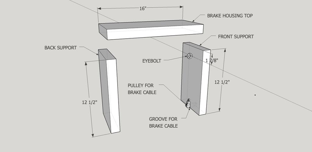
figure sk-10
The brakes consist of three components, the housing, the arm and linkage assembly, and the pedal. The housing is made up of two supports and a top piece, as shown in figure sk-10. Note that front support has a pulley and an eyebolt installed.
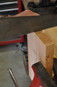
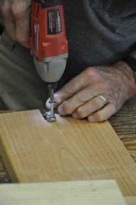
Cut a notch on the middle of the end of one of the supports. Mount a pulley in this notch. This is for the brake cable. This support goes in the forward position with the pulley over the hole in the frame for the brake arm. Drill pilot holes for the support and fasten with 3″ wood screws. Mount the rear support to the frame in the same manner per dimensions on sk-10.
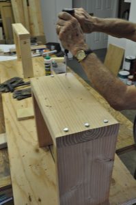
Install the two housing supports to the frame with wood screws from underneath the frame as shown in figure sk-11.
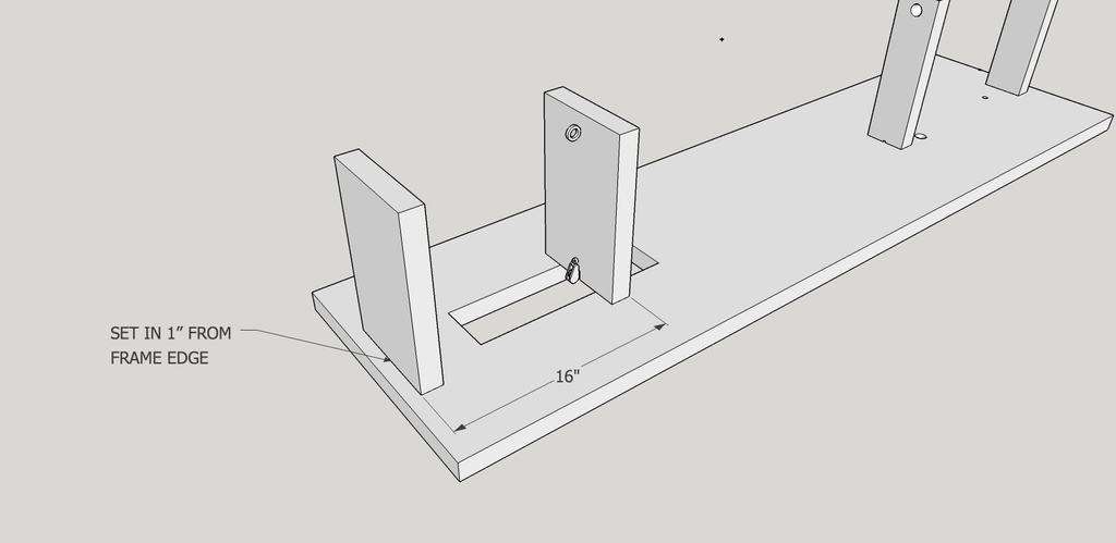
figure sk-11